Rc Low Pass Filter Circuit Diagram Fig. 1. Rc Circuit Config
High pass rc filter Filter pass low rc frequency circuit simple high integrator lpf diagram response electronics Active low-pass rc filter circuit diagram
simulation - Trouble calculating transfer function of 3rd order RC
Draw the rc low pass filter circuit diagram prompts Series rc low pass filter-electrical circuit analysis-lecture slides Filter rc series circuit pass low response multisim verify given software designed ac following let
Electronic – what’s the difference between these two low pass filter
Low-pass and high-pass filters (explanation and examples)Series rc circuit design [a low pass filter 2024] Rc low pass filter circuit diagramPassive filters.
Low pass filters and high pass filtersPass low rc rl filter frequency circuit filters cutoff 3a figure electricalacademia Solved how to use a rc circuit to build a low pass filterMenschlich schluchzen radioaktivität low pass filter experiment.

Low pass filter : circuit, types, calculators & its applications
Filter circuit diagram pdfFilter pass low circuit active simple make subwoofer circuits homemade 741 using diagram ic electronics here projects gr next woofer Describe the circuit and operation of an active low pass filter withLow pass filter bode plot indus, electrical engineering, filters, no.
Simple rc low pass filter circuit diagram with frequency responseSimple rc low pass filter circuit diagram with frequency response Rc low pass filter circuit diagramLow pass filter diagram.
![Series RC circuit Design [A Low Pass Filter 2024]](https://i2.wp.com/www.yamanelectronics.com/wp-content/uploads/2018/09/1-9.jpg)
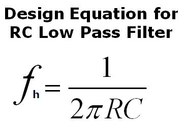
Filter pass low response passive frequency rc order filters diagram signal bode circuit electronics plot draw first ws tutorials equation
Fig. 1. rc circuit configuration of low pass filter.Passive high pass filter circuit diagram Circuit filter rc pass low active diagramDraw an rc low pass filter circuit in circuitikz.
Filter pass low rc lowpass filters frequency high cut off inductor radioRc low pass filter circuit Rc passive low-pass filterPass low rc filter breadboard high filters analog wiki activity connections figure.

Activity: low pass and high pass filters, for adalm1000 [analog devices
Active low pass filter circuit diagram wiring view and schematicsLow pass filter design – engineering radio Filter pass low rc circuit diagram lpf simple frequency basic integrator circuits response capacitor components required resistor valuesSeries rc circuit and its design [a low pass filter].
Filter pass low circuit active diagram frequency response operation op amp gain neat describe only principle exactly itsPass filter low rc circuit input step figure integrator rectangular sinusoidal Pass rc rl circuitsFrequency passive butterworth electronicshub amplifier blocking theory frequencies.
Active low pass filter circuit diagram
Rc and rl low pass filterLow pass filter circuit for subwoofer – homemade circuit projects Subwoofer low pass filter circuit diagramInformationen zur einstellung sensor konsonant how to design a low pass.
.


Informationen zur Einstellung Sensor Konsonant how to design a low pass

Solved How to use a RC circuit to build a low pass filter | Chegg.com

RC Low Pass Filter Circuit - As integrator, step input, rectangular

Low Pass Filter Bode Plot Indus, Electrical Engineering, Filters, No

simulation - Trouble calculating transfer function of 3rd order RC

Low Pass Filter design – Engineering Radio
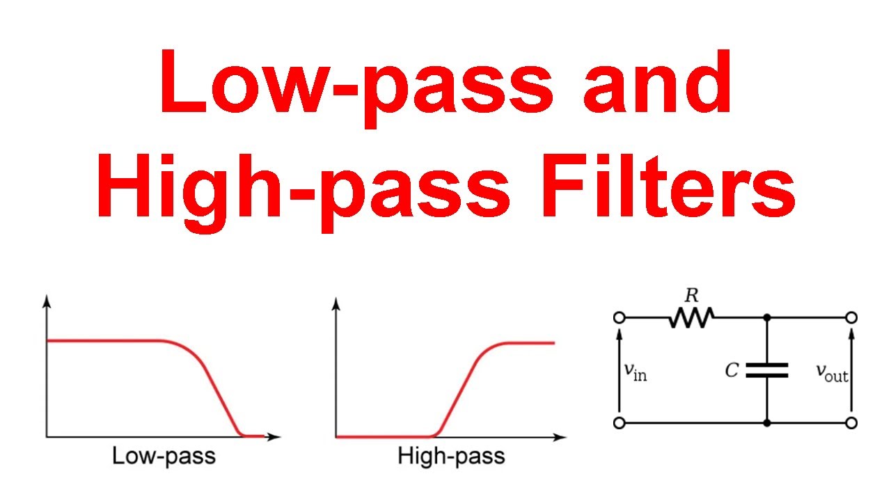
Low-pass and High-pass Filters (Explanation and Examples) - YouTube